

Showing posts with label Texturing. Show all posts

CUSTOMIZING YOUR WOOD FLOOR - PARQUET MATERIAL
Saturday, October 18, 2008
Introduction:
Floor is one of the elements contained in Architecture. Floor Covering Materials are several kinds, such as, concrete, ceramics, marble, steel plate, glass, wood, and etc. One of the floor covering material that we will learn is the wood. There are 2(two) Wood Floor Form, regular, and irregular form. As a form of regularity; collated row, and a row, this form of a general often found on the pier wood floor, this form of order and the board tend to be rigid. While the form of irregularly used to show effects thus do not feel certain monoton, for example, on the parquet floor. This tutorial will guide you on how to make the cover material from the wood floors (parquet), and I assume that this tutorial is intended for the beginner level and understand the use of basic software on the'3dsMax ' very well.
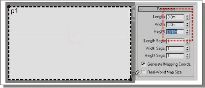
1) Go to 3dsMax software, and start by creating a box with the size of a thick; 0:02 m, 5 m in length and width of 3 m. (on the scale of the size of the box that we will use as a floor, you can set you up). Then give the name of the object box with the 'floor'.
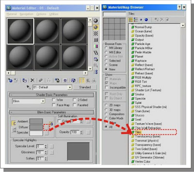
2) Press' M 'on your keyboard to display the Material / Map Browser,' then change the settings without any application of material standard slot on the objects' floor '. Click the left slot on the material standards, hold, then slowly move the object on the 'floor'. Back in the Material / Map Browser, click on the 'diffuse' so it appears a 'floating bar' new slide 'slidebar' to down to the choice of 'Tiles' left click twice to applicate it to the material.
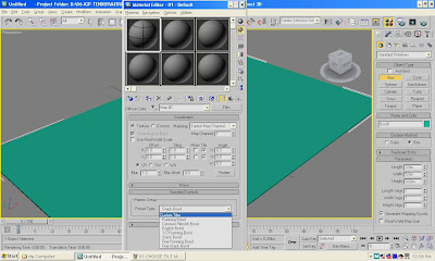
3) Once selected, in the 'Standard Controls' select' Custom Tiles '.
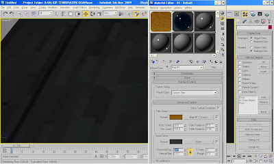
4) In the 'Advanced Controls' values change from the' horiz and Vert Count 'to; 20 for' horiz Count 'and 100 in the' Vert Count '. besides that, change the 'Color variance' to 0.5, 'Horizontal Gap' and 'Vertical Gap' to 0:01. (This step is to set the scale pattern that will become a reference for the texture of the object).
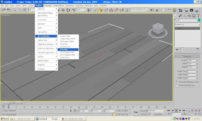
5) Then we will create 'UVW Map' menu by selecting 'modifier', 'UV Coordinates,' and select 'UVW Map' (This step is the implementation of how the size scale of the texture of the object. Remember the value of the amount must be greater than the size of the object was 3 mx 5 m so that the texture is done repeatedly, but not monoton).
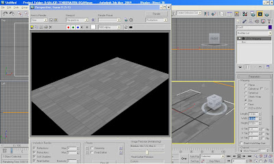
6) Select 'Mapping' box on the 'Sidebar Menu' to the right of the screen, visible 'UVW Map Paremeters', and change paremeters to 10 m for' Length 'and 10 m for' Width '.
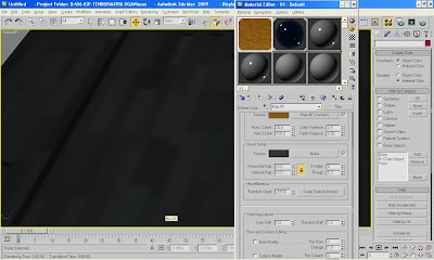
7) Click the '-' in the 'Standard Control' to undermine the menu. And on the menu 'Advanced Controls' slide' sidebar 'slow-down menu to' Stacking layout '. Modifications' Line Shift 'and' Random Shift to be 0.0 and 1.2. (This step is to change the basic pattern that we will use that to be random and not uniform).
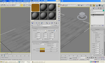
8) Back in the 'Tiles setup', click on the left side of the box 'none' to the new menu appears. Then gently slide the 'sidebar' down to the 'Wood,' and left click twice to apply. Once the menu appears Material Editor 'change options' Source' to "Explicit Channel Map 'and' Map Channel 'to 2, and' Grain Thickness' to 2.5. (This step is to create a 'layer' in the new 'Tile Map' with the motive timber).

09) To complete the defenition from 'Explicit Channel Map' 2, make 'UVW Map' over new 'UVW Map' existing. Select 'Mapping' box on the 'Sidebar Menu' to the right of the screen, visible 'UVW Map Paremeters', and change paremeters to 10 m for' Length 'and 10 m for' Width '..
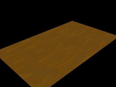
10) Then press' F9 'to see the results of' rendering 'temporary. Well, enough already seen what we have modifications required?
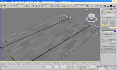
11) To have the texture of the object can be seen on the screen, create a light 'Omni' on the screen. Then specify its position above the objects' floor 'so that the texture can be seen properly.
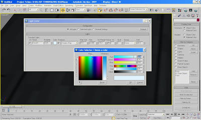
12) Make modifications in the light paremeter 'Omni' menu by pressing 'tools', and' Light Lister 'as shown in the picture above.
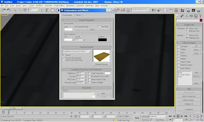
13) To make the environment a more realistic texture, specify the options' Exposure Control 'by pressing'8' on the keyboard. Select 'Logaritmic Exposure Control' and change paremeter appropriate image.
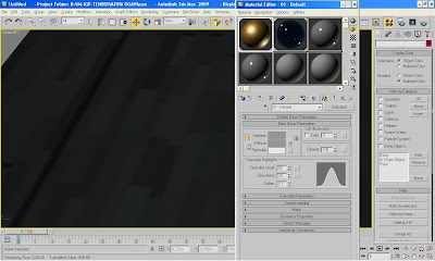
14) Back in the Material Editor 'with the' M ', change' Specular Highlight Paremeter 'to 80 for' Specular Level 'and 20 for' Glossiness'. (This step is to create the texture of the object 'floor' to become more shiny, reflective and slightly).
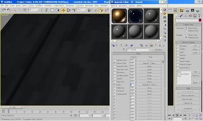
15) Still on the options' Material Editor 'slide' slidebar 'to the menu' Maps', then copy the 'Diffuse Color' menu to 'Bump' with the way the left click 'Map # 1 (Tiles)' on 'Diffuse Color' resistance click on the left and gently slide down to the 'Bump'. (This step is done to create objects become visible, such as three-dimensional (3d)).
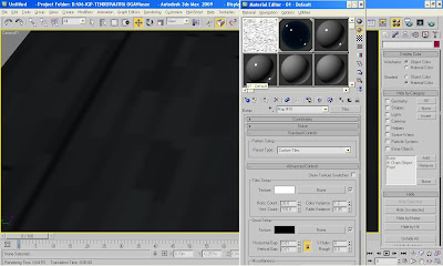
16) Click setting 'Bump' which is copied, change the color texture into 'white', and 'grout Setup' to the color of 'black'.
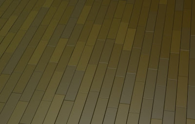
17) You can see the results of this tutorial.
Floor is one of the elements contained in Architecture. Floor Covering Materials are several kinds, such as, concrete, ceramics, marble, steel plate, glass, wood, and etc. One of the floor covering material that we will learn is the wood. There are 2(two) Wood Floor Form, regular, and irregular form. As a form of regularity; collated row, and a row, this form of a general often found on the pier wood floor, this form of order and the board tend to be rigid. While the form of irregularly used to show effects thus do not feel certain monoton, for example, on the parquet floor. This tutorial will guide you on how to make the cover material from the wood floors (parquet), and I assume that this tutorial is intended for the beginner level and understand the use of basic software on the'3dsMax ' very well.

1) Go to 3dsMax software, and start by creating a box with the size of a thick; 0:02 m, 5 m in length and width of 3 m. (on the scale of the size of the box that we will use as a floor, you can set you up). Then give the name of the object box with the 'floor'.

2) Press' M 'on your keyboard to display the Material / Map Browser,' then change the settings without any application of material standard slot on the objects' floor '. Click the left slot on the material standards, hold, then slowly move the object on the 'floor'. Back in the Material / Map Browser, click on the 'diffuse' so it appears a 'floating bar' new slide 'slidebar' to down to the choice of 'Tiles' left click twice to applicate it to the material.

3) Once selected, in the 'Standard Controls' select' Custom Tiles '.

4) In the 'Advanced Controls' values change from the' horiz and Vert Count 'to; 20 for' horiz Count 'and 100 in the' Vert Count '. besides that, change the 'Color variance' to 0.5, 'Horizontal Gap' and 'Vertical Gap' to 0:01. (This step is to set the scale pattern that will become a reference for the texture of the object).

5) Then we will create 'UVW Map' menu by selecting 'modifier', 'UV Coordinates,' and select 'UVW Map' (This step is the implementation of how the size scale of the texture of the object. Remember the value of the amount must be greater than the size of the object was 3 mx 5 m so that the texture is done repeatedly, but not monoton).

6) Select 'Mapping' box on the 'Sidebar Menu' to the right of the screen, visible 'UVW Map Paremeters', and change paremeters to 10 m for' Length 'and 10 m for' Width '.

7) Click the '-' in the 'Standard Control' to undermine the menu. And on the menu 'Advanced Controls' slide' sidebar 'slow-down menu to' Stacking layout '. Modifications' Line Shift 'and' Random Shift to be 0.0 and 1.2. (This step is to change the basic pattern that we will use that to be random and not uniform).

8) Back in the 'Tiles setup', click on the left side of the box 'none' to the new menu appears. Then gently slide the 'sidebar' down to the 'Wood,' and left click twice to apply. Once the menu appears Material Editor 'change options' Source' to "Explicit Channel Map 'and' Map Channel 'to 2, and' Grain Thickness' to 2.5. (This step is to create a 'layer' in the new 'Tile Map' with the motive timber).

09) To complete the defenition from 'Explicit Channel Map' 2, make 'UVW Map' over new 'UVW Map' existing. Select 'Mapping' box on the 'Sidebar Menu' to the right of the screen, visible 'UVW Map Paremeters', and change paremeters to 10 m for' Length 'and 10 m for' Width '..

10) Then press' F9 'to see the results of' rendering 'temporary. Well, enough already seen what we have modifications required?

11) To have the texture of the object can be seen on the screen, create a light 'Omni' on the screen. Then specify its position above the objects' floor 'so that the texture can be seen properly.

12) Make modifications in the light paremeter 'Omni' menu by pressing 'tools', and' Light Lister 'as shown in the picture above.

13) To make the environment a more realistic texture, specify the options' Exposure Control 'by pressing'8' on the keyboard. Select 'Logaritmic Exposure Control' and change paremeter appropriate image.

14) Back in the Material Editor 'with the' M ', change' Specular Highlight Paremeter 'to 80 for' Specular Level 'and 20 for' Glossiness'. (This step is to create the texture of the object 'floor' to become more shiny, reflective and slightly).

15) Still on the options' Material Editor 'slide' slidebar 'to the menu' Maps', then copy the 'Diffuse Color' menu to 'Bump' with the way the left click 'Map # 1 (Tiles)' on 'Diffuse Color' resistance click on the left and gently slide down to the 'Bump'. (This step is done to create objects become visible, such as three-dimensional (3d)).

16) Click setting 'Bump' which is copied, change the color texture into 'white', and 'grout Setup' to the color of 'black'.

17) You can see the results of this tutorial.

TEXTURING YOUR BRICK MATERIAL STEP BY STEP
Friday, October 3, 2008
Brick is one of the Popular material that we usually often used in 3ds Max world. The brick’s application as wall constructor or wall exspose. Behind as Architectural element, the bricks usually used in the Game and Industry. This tutorial will guide u how to make your own bricks material step by step, and I assume that it really works for the beginner, and have a great understanding of basic geometry. Enjoy it.
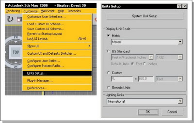
1). First, we have to made some decision to use Default Standard Unit that we have. I use Metric Unit, especially in Meter, if u usually often use inch and feet u can use it too. with some modification.
choose CUSTOMIZE >>> UNITS SETUP
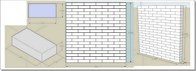
2). Then, we have try to understanding the brick’s material module, I use brick’s module in length 20 cm, width 10 cm, and height 5 cm. this module’ll be used to fill the Main Material Module as the wall’s texture. In this case, I use square unit (m2), so amount of brick’s module for square are 100 pieces, with the composition in 5 horisontal line, and 10 vertical line row. With this square module, that we used for any variable dimentional wall, so the basic square module’ll be match it. To understanding that, u can see this picture ;
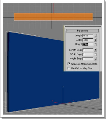
3). After that, we go to 3ds Max. Make a box with the length and height what ever u wanted, but still use the width in 10 cm. in this tutorial I use dimention in length 4 m, width 0.1 m, and height 2 m.
4). Open up the Material Browser, choose the Default Shader, and applied it to wall.
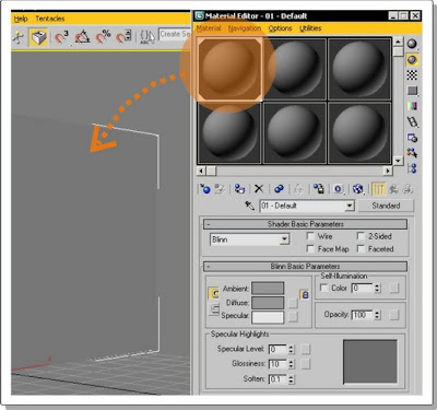
5). Create an Omni to light up the wall, do some modification such as; change the light’s position to made the wall clearly sight, then change the Omni’s Basic Paremeter, decrease the light intensity, and change the light color too.
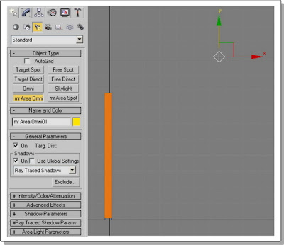
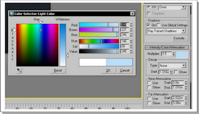
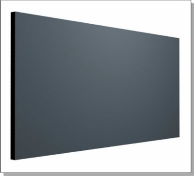
6). After the light ready, keep on to modificate the tile’s material which is as the wall’s maodule.

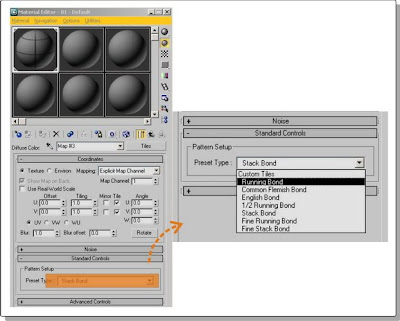
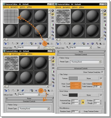
7) Non activated End Result Material, so the brick’s pattern looks clearly, then have some modification in Horizontal Count’s paremeter to 5, and the vertical Count to 10. This module that’ll be used as our basic pattern, then change the Color Variance’s paremeter to 0.75, so the pattern not really looks monoton.
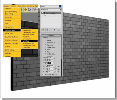
8). To fit the brick’s material to exsisting wall, use UVW Map, and choose box. Then change the width and heigh paremeters to 1 m. This setting will be used as main pattern for the brick’s wall how many the dimention is, the pattern still in square module with Tile Map pattern.
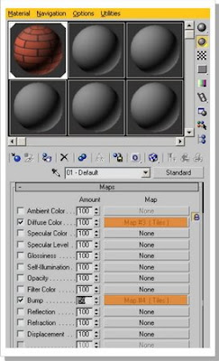
9). For better result, made some modification, tile texture could be matched color u like, and the emboss effect can be produced with the bump map. After that, back to the material/map browser, in sub map copy the diffuse setting to bump setting and change the paremeter to 50


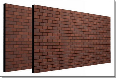
10). Last step is render the scene to get the final render
1). First, we have to made some decision to use Default Standard Unit that we have. I use Metric Unit, especially in Meter, if u usually often use inch and feet u can use it too. with some modification.
choose CUSTOMIZE >>> UNITS SETUP

2). Then, we have try to understanding the brick’s material module, I use brick’s module in length 20 cm, width 10 cm, and height 5 cm. this module’ll be used to fill the Main Material Module as the wall’s texture. In this case, I use square unit (m2), so amount of brick’s module for square are 100 pieces, with the composition in 5 horisontal line, and 10 vertical line row. With this square module, that we used for any variable dimentional wall, so the basic square module’ll be match it. To understanding that, u can see this picture ;

3). After that, we go to 3ds Max. Make a box with the length and height what ever u wanted, but still use the width in 10 cm. in this tutorial I use dimention in length 4 m, width 0.1 m, and height 2 m.

4). Open up the Material Browser, choose the Default Shader, and applied it to wall.

5). Create an Omni to light up the wall, do some modification such as; change the light’s position to made the wall clearly sight, then change the Omni’s Basic Paremeter, decrease the light intensity, and change the light color too.


6). After the light ready, keep on to modificate the tile’s material which is as the wall’s maodule.


7) Non activated End Result Material, so the brick’s pattern looks clearly, then have some modification in Horizontal Count’s paremeter to 5, and the vertical Count to 10. This module that’ll be used as our basic pattern, then change the Color Variance’s paremeter to 0.75, so the pattern not really looks monoton.

8). To fit the brick’s material to exsisting wall, use UVW Map, and choose box. Then change the width and heigh paremeters to 1 m. This setting will be used as main pattern for the brick’s wall how many the dimention is, the pattern still in square module with Tile Map pattern.

9). For better result, made some modification, tile texture could be matched color u like, and the emboss effect can be produced with the bump map. After that, back to the material/map browser, in sub map copy the diffuse setting to bump setting and change the paremeter to 50


10). Last step is render the scene to get the final render

BASIC CAUSTIC WITH VRAY PLUGINS
Thursday, October 2, 2008

in this tutorial, we'd better using 3ds max's plug ins, V-Ray
i setup the scene, create a box, and a torus knot
added a spot light
- shadows on (vray shadows)
- under vray parameters check the smooth surface shadows
i’m not gonna explain everything what i did, you can see for you self if you download the scene
and render the scene out, you should have something like :

now first off we’ll create some materials, so get into the material editor and seleect a new material, change it it vray material
- change reflection and refraction color to white
- check Fresnel reflections
- choose a very licht blue color as Fog color
- set fog multi. to 0.01
- check Affect shadows
assign it to the torus knot
now create a other material, also a vray material
for diffuse color select a light grey
and if you render you have something like this :

now we are missing the caustics, here we go:
get your vray renderer and goto vray:system
click light settings and select spot01
click “generate caustics” on
subdivs : 2500
multi : 100000.0
now go back to the render dialog and search for vray:caustic tab
click “on”
multi. : 4
search dist. : 0.4
max photon : 2000
and render it out you should get something like :

to get some better caustics change to
multi. : 2
search dist. : 0.4
max photon : 2500
also change the under vray:system -> lightsettings > spot01 caustics subdive to 5000
also add a meshsmooth to the torus (render Iter. 2)
then render it out
this is gonna take long, calculating the caustics but well,

source : http://www.cg-files.com/
WATER MATERIAL WITH VRAY PLUGINS
in this tutorial, we'd better using 3ds max's plug ins, V-Ray.
1. Open Material Editor by pressing M on your keyboard.
2. Click on Get Material button, and chouse Vray material from Materail/Map Browser
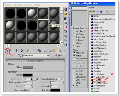
3. Rename material to “Water”
4. Click on Diffuse color, and set to black.

5. For the Reflect color use this settings: Red 232, Blue 232, Green 232
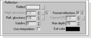
6. In the Refraction menu change Refract color to pure white and change Max depth to 10. See picture below.
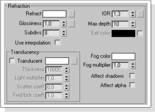
7. Scroll down and find Options menu. Just turn on “Reflect on back side”
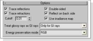
That is all. Like I said this material is for V-ray. Just to know, results of this material while you render also depend from your Render and Lighting settings
source : http://www.cg-files.com/
1. Open Material Editor by pressing M on your keyboard.
2. Click on Get Material button, and chouse Vray material from Materail/Map Browser

3. Rename material to “Water”
4. Click on Diffuse color, and set to black.

5. For the Reflect color use this settings: Red 232, Blue 232, Green 232

6. In the Refraction menu change Refract color to pure white and change Max depth to 10. See picture below.

7. Scroll down and find Options menu. Just turn on “Reflect on back side”

That is all. Like I said this material is for V-ray. Just to know, results of this material while you render also depend from your Render and Lighting settings
source : http://www.cg-files.com/
TEXTURING UVW AND UNWRAP UVW MAPS
 This tutorial'll teach u a couple of methods to use to texture ur objects in 3ds Max. Texturing an object is understood as the process of adding skin and colour to an object. We're goin' to use UVW and Unwrap UVW Maps to texture ur objects in this tutorial. This method involves the creation of 2D map that's 'glued' to our 3D model. You're assumed to have the basic knowledge on how to model your own objects in 3ds Max.
Part I - Create and Apply Textures using UVW and UnWrap UVW Maps
The first part of this tutorial will teach you how to texture using UVW and UnWrap UVW Maps. Using this method we will first apply standard materials to certain parts of our model to distinguish between different parts of it and then make 2D UVW Maps out of these models that we can edit using any external image editor. These images created using our external image editor are then easily applied to our materials to fit perfectly on our model. The procedure will now be explained step by step.
Open the file that you downloaded, you should see the model on the screen. We will first texture the house only, so start off by hiding all the other objects on the scene. You do this by clicking on the Display Tab, and accessing the Hide panel from there.
 Use We will start by applying generic materials to distinguish between the different parts of the model, we have to create these before we apply them. Hit "M" on your keyboard to open the "Material Editor". Select a free a slot in there and change the type from "Standard" to "Multi/Sub-Object". Name the material "House" (We are going to texture the body of the house first).
Notice that you get 10 Sub-Materials by default, change that to 6 and click on "Set Number". Name the Sub-Materials below in accordance to the different walls the house house, for the sake of the tutorial, name them in this order: Front, Back, Left, Right, Top, Rest. Notice the ID Number next to each of the Sub-Materials, we are going to use this later on. For now however, change the colour of each material using the "Colour Selector", just use a different colour for each of the materials, we need to distinguish them from each other.
 It is now time to assign the materials that we have created to our model. Click on the "Assign To Selected" button (). In the "Modify Tab", change the selection mode to "Polygon", now select all the outer polygons of the front wall of the house by holding CTRL and then selecting the walls, make sure you don't select the inner polygons of the windows and the door though. Now that you have the front wall selected, find the "Polygon Properties" rollout menu, and set the "SetID" field to "1". The number 1 here is the ID Number of the Sub-Material we created earlier on for the front wall of the house, putting this ID number should assign the material that we created earlier to this part of the house.
Repeat the same process for the other four parts of the house (Back, Left, Right, and Top). You do this by selecting the polygons on a single wall and then setting the Material ID to them accordingly. If you have named your layers in the order that we suggested you should put these values to your walls, Back: ID 2, Right: ID 3, Left: ID 4, Top: ID 5. The rest of the polygons should be assigned to material ID 6.
 We now have different materials assigned to the different parts of our model. The next stage is creating textures for those Sub-Materials and then mapping them to the object. We will have to create a separate UVW Map for each of our materials, doing them on a turn, we will select the material, create a UVW Map, edit the map using an external image editor, and the map the texture to the object.
Select the house by clicking once on it and then access the "Modify Tab", and select the "Select Mesh" entry the "Modifier List". Change the selection mode to "Polygon", the enter the number "1" in the "Select Material by ID" field and then click on "Select" to select only the front wall part of the house.
 We will now add a UVW Map to the material we selected. Select the "UVW Map" entry from the "Modifier List", make sure it goes above the "Select Mesh" entry that we created earlier. Scroll down below and find the "Alignment" parameters, select "X" to align the projector map to the X-Axis and then click on "Fit" to make it the same size as the selected polygons. Finally, we have to make dimensions of the projector map a perfect square, because otherwise our UVW map will be distorted as it gest stretched to make a square when used. We can easily make the original dimensions of our map a square by pasting the value of the length as a the width as well. (Check the image below)
 We will now create our Unwrap Map, select the "Unwrap Map" entry from the "Modifier List". Find the Parameter" rollout menu and then click on "Edit". You should see the UVW Mapping for the selected polygons only in the Edit UVWs window. This is the front wall of the house, notice the holes in the centre that make up the windows and the door.
 If u're making ur own model & texture from scratch u'd have to copy this image and paste it in ur image editing software to draw ur map there. You can simply press Alt+Print Screen to take a snap shot of the active window. Pasting this in an image editor and then using the screenshot as a reference should be an easy job. Notice how I draw the texture on the wall in accordance to the holes that make up the windows and the door. Once u're done with it, save your new map as a JPG image. u don't have to do this for this tutorial as we have provided u with all the textures u need, but now u should know how to make these on ur own.
 Back to 3ds Max now, open the "Material Editor" and select the "House" Material. Click on the Sub-Material "Front", this should open up the properties panel of the material, click on the box next to "Diffuse", select "Bitmap" and then locate the image of the front wall (You downloaded this). The texture should be already applied now to the front wall of the house, click on the "View in Viewport" button () in the "Material Editor"to be able to view what you have just done in the view port.
Our first wall is done! it looks cool. u can repeat the process for the rest of the walls of the house, here's a small reminder:
1. Select the "Select Mesh" entry from they "Modifier List" in the "Modify Tab". Select the polygons "by Material" enter the ID number of the material used, e.g. "2" for the "back" wall.
2. Select the "UVW Map" entry from the "Modifier List", align the projector to selected polygons, resize the projector map by fitting it to the selected polygons, and finally make sure that the project map size is a
perfect square in dimensions.
3. Select the "Unwrap Map" entry from the "Modifier List", click on "Edit" to open the "Edit UVWs Window".
4. Take the screenshot of this and edit it using an external image editing software, draw the texture on it.
5. Open the "Material Editor", select material ID for the texture, and locate the texture that you have for it.
The files for these textures have been included in the file that you have downloaded at the beginning of this tutorial. I made a texture for the chimney as well, you can unhide it from the Display Tab and then apply the material to it the same way you did to the walls.

Once you're done, unhide all the objects and you should get a similar scene to the one displayed below.

Source : http://www.oman3d.com/


